Question
a.
90°
b.
60°
c.
45°
d.
30°
Posted under Electronics and Communication Engineering
Interact with the Community - Share Your Thoughts
Uncertain About the Answer? Seek Clarification Here.
Understand the Explanation? Include it Here.
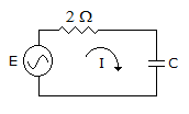
Q. In figure, E = 1 V (rms value). The average power is 250 mW. Then phase angle between E and I is
Similar Questions
Explore Relevant Multiple Choice Questions (MCQs)
Q. Given Is = 20 A, Vs = 20 V, the current I in the 3 Ω resistance is given by
View solution
Q. For the three coupled coils shown in figure, KVL equation is
View solution
Q. Figure shows a dc circuit. The Thevenin's equivalent circuit at terminals a - b is
View solution
Q. The dependent current source shown in given figure.
View solution
Q. The current flowing through the resistance R in the circuit in the figure has the form 2 cos 4t, where R is
View solution
Q. A triangular Pulse of 10 V peak is applied to a capacitor of 0.4 F. The change of the capacitor and its waveform is
View solution
Q. In figure, the current after a long time after closing of switch is
View solution
Q. In figure, power in 6 Ω resistor is zero then V =
View solution
Q. The Thevenin's equivalent of network in figure(1) is a 10 V source in series with 2 Ω resistance. If a 3 Ω resistance is connected across AB as shown in figure(2) the Thevenin's equivalent is
View solution
Q. In the circuit shown in the figure, the current supplied by the sinusoidal current source I is
View solution
Q. If figure, power dissipated in 30Ω resistance will be maximum when value of R =
View solution
Q. In the following non-planar graph no.of independent loop equations are
View solution
Q. For an RLC series circuit, Z(s) will be of the form of
View solution
Q. In the circuit shown in the figure, steady-state was reached when the switch S was open. The switch was closed at t = 0. The initial value of the current through the capacitor 2 C is
View solution
Q. A system function given by the following equation, the resonant frequency in rad/sec and bandwidth in rad/sec is given by
View solution
Q. The reading of the voltmeter in figure will be __________ volt.
View solution
Q. Find RL for maximum power transfer
View solution
Q. In figure, the voltmeter is ideal. The transformer has two identical windings with perfect coupling. The reading of voltmeter is
View solution
Q. The final value of following equation is
View solution
Q. The resistance of the circuit shown is figure is
View solution
Recommended Subjects
Are you eager to expand your knowledge beyond Electronics and Communication Engineering? We've handpicked a range of related categories that you might find intriguing.
Click on the categories below to discover a wealth of MCQs and enrich your understanding of various subjects. Happy exploring!