Question

a.
indeterminate due to indeterminate data
b.
zero
c.
4 Amp
d.
8 Amp
Posted under Electronics and Communication Engineering
Interact with the Community - Share Your Thoughts
Uncertain About the Answer? Seek Clarification Here.
Understand the Explanation? Include it Here.
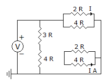
Q. For the circuit shown in the figure, the current I is
Similar Questions
Explore Relevant Multiple Choice Questions (MCQs)
Q. The current voltage relation for an inductance L is
View solution
Q. In figure, the steady state current through 1H inductance is
View solution
Q. Impedance Z as shown in the given figure is
View solution
Q. In figure, the value of R should be
View solution
Q. In figure the open circuit emf is
View solution
Q. If
View solution
Q. The pole zero diagram of an impedance Z has a pole at s = - 6 and zero at s = - 4 as shown in figure the constant multiplier k = 1. For a signal Is = cos 6t, the steady state voltage across Z is given in magnitude as under
View solution
Q. In the circuit of figure the current through 5 Ω resistance at t = 0+ is
View solution
Q. v-i relation for a capacitor is
View solution
Q. The time constant of the circuit in figure is
View solution
Q. The damping coefficient for the given circuit is __________
View solution
Q. For the ladder network of figure, open circuit driving point impedance at port 1 =
View solution
Q. If Va0, Va1, Va2 are sequence components of Va and Ia0, Ia1, Ia2 are sequence components of Ia, then total 3 phase power P is given by
View solution
Q. In the circuit of figure the current through 3 Ω resistance at t = 0+ is
View solution
Q. Assertion (A): For networks in figure (1) and (2) sum of products of branch voltages and branch currents at any time is zero.
Reason (R): The networks in figure (1) and (2) are not the same structurally.
View solution
Q. In the circuit of figure the switch is open for a long time, At t = 0 the switch is closed. At t = 0+ the current supplied by battery is
View solution
Q. An RL series circuit is initially relaxed. A step voltage E is applied. If t is time constant, voltage across R and L will be equal at t =
View solution
Q. For the two port of figure, z11 is
View solution
Q. If the π and T circuits in figure are equivalent, then R1, R2, R3 respectively are
View solution
Q. In the circuit, Vs = 10 cos ωt, power drawn by the 4Ω resistor is 8 watt. The power factor is
View solution
Recommended Subjects
Are you eager to expand your knowledge beyond Electronics and Communication Engineering? We've handpicked a range of related categories that you might find intriguing.
Click on the categories below to discover a wealth of MCQs and enrich your understanding of various subjects. Happy exploring!


