Question
a.
s + 1/4
b.
s + 4
c.
4s + 1
d.
s + 16
Posted under Electronics and Communication Engineering
Interact with the Community - Share Your Thoughts
Uncertain About the Answer? Seek Clarification Here.
Understand the Explanation? Include it Here.
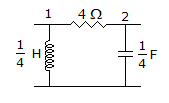
Q. For the port shown, the short circuit network function at port 2 is given by
Similar Questions
Explore Relevant Multiple Choice Questions (MCQs)
Q. A series RL circuit is initially relaxed. A step voltage is applied to the circuit. If t is the time constant of the circuit, the voltage across R and L will be same at time t equal to
View solution
Q. In figure, the transmission parameters are A = C = 1, B = 2 and D = 3. Then Zin =
View solution
Q. A sinusoidal voltage is written as v = Im (R² + XC²)^0.5 sin 314 t. Its peak value and frequency are
View solution
Q. KVL equation for the circuit of figure is
View solution
Q. In figure the rms value is
View solution
Q. The frequency at which maximum voltage occurs across the inductance in R-L-C series circuit is
View solution
Q. In figure, the value of R should be
View solution
Q. In the network shown in figure, the voltage drops across R2 and R3 are 10 V and 16 V with polarities as shown. The current in R1
View solution
Q. The V-i relation for a varistor is
View solution
Q. The energy dissipated W in a resistance having voltages v and current i is given by
View solution
Q. In figure, the current through 2 Ω resistance is
View solution
Q. The frequency at which maximum voltage occurs across the capacitance in R-L-C series circuits is given by
View solution
Q. At resonance, the parallel circuit constituted by an iron-cored coil and a capacitor behaves like
View solution
Q. In figure, the current I
View solution
Q. Which of the following is/are correct? The circuit shown in the figure.
1. is reciprocal
2. has Z11 = 2, Z22 = 2
3. has Z11 = 4, Z22 = 2
4. has Z11 = 0, Z22 = 2
Select the correct answer using the code given below:
View solution
Q. In the figure shown, assume that all the capacitors are initially unchanged and Vi(t) = 10 U(t) volts then V0(t) is given by
View solution
Q. For the network in figure, the correct loop equation for loop 3 is
View solution
Q. In the below circuit, if the power dissipated in the 6 Ω resistor is zero then V is
View solution
Q. In figure, the switch S is initially open and steady state conditions are reached. At t = 0 switch is closed. The initial current through 2C capacitor is
View solution
Q. In the circuit of figure the current through 5 Ω resistance at t = ∞ is
View solution
Recommended Subjects
Are you eager to expand your knowledge beyond Electronics and Communication Engineering? We've handpicked a range of related categories that you might find intriguing.
Click on the categories below to discover a wealth of MCQs and enrich your understanding of various subjects. Happy exploring!