Question
a.
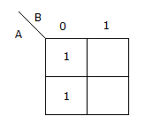
A̅ B̅ + A B̅
b.
B̅
c.
A̅
d.
A B̅
Posted under Electronics and Communication Engineering
Interact with the Community - Share Your Thoughts
Uncertain About the Answer? Seek Clarification Here.
Understand the Explanation? Include it Here.
Q. For the K map of the given figure the simplified Boolean expression is
Similar Questions
Explore Relevant Multiple Choice Questions (MCQs)
Q. Unlimited number of ICs 7490, 78492 and 7493 are available. Which of these could be used to build the dividse-by-60 circuit of figure
View solution
Q. The contents of the program counter after the call operation point to the first instruction on the
View solution
Q. The logic circuit in the given figure realizes the function
View solution
Q. An n bit ADC using Vr as reference has a resolution (in volts) of
View solution
Q. The logic performed by the high-noise immunity logic circuit shown below is
View solution
Q. The contents of the program counter after the call operation will be
View solution
Q. In 8085 microprocessor, an active low signal INTA is not needed from up service which of the following interrupt request?
View solution
Q. For the K map in the given figure, the simplified expression is
View solution
Q. The stack is a specialized temporary __________ access memory during __________ and __________ instructions.
The 8156 of a figure has RAM locations from 2000 H to 20 FFH.
View solution
Q. The counter shown in the given figure is
View solution
Q. The Truth Table shown is for a
View solution
Q. The simplified logic expression for the circuit of the given figure is
View solution
Q. DeMorgan's first theorem is =
View solution
Q. Consider the following digital circuits:
1. Multipliers
2. Read only memories
3. D-latch
4. Circuits as shown in figure
Which of these come under the class of combinational circuit?
View solution
Q. The open wired circuit in the given figure works as a
View solution
Q. The circuit shown below is functionally equivalent to
View solution
Q. The clock shown in figure has a frequency of 6 MHz. The frequency of the Q output will be
View solution
Q. If all bubbles are removed, what are the new RAM locations?
The 8156 of a figure has RAM locations from 2000 H to 20 FFH.
View solution
Q. The logic operations of the two circuits given below are
View solution
Q. A 3 stage Johnson counter (ring) shown in figure is clocked at a constant frequency of fc from the starting state of Q₀ Q₁ Q₂ = 101. The frequency of output Q₀ Q₁ Q₂ will be
View solution
Recommended Subjects
Are you eager to expand your knowledge beyond Electronics and Communication Engineering? We've handpicked a range of related categories that you might find intriguing.
Click on the categories below to discover a wealth of MCQs and enrich your understanding of various subjects. Happy exploring!