Question
a.
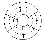
The radial lines are E lines and circular lines are H lines
b.
Radial lines are H lines and circular lines are E lines
c.
The directions of E and H lines are wrong
d.
Radial lines may be E and H lines depending an direction of current
Posted under Electronics and Communication Engineering
Interact with the Community - Share Your Thoughts
Uncertain About the Answer? Seek Clarification Here.
Understand the Explanation? Include it Here.
Q. In the given figure the E and H lines in a coaxial cable
Similar Questions
Explore Relevant Multiple Choice Questions (MCQs)
Q. When a line is loaded the characteristic impedance is equal to
View solution
Q. In the given figure forward current wave has a magnitude of
View solution
Q. In the given figure shows the equivalent circuit of a magic tee. If all ports are matched
View solution
Q. In the given figure forward voltage wave has a magnitude
View solution
Q. For a rectangular waveguide having width a and height b, the cutoff wavelength for TM₁₁ mode is equal to
View solution
Q. If ZTE is wave impedance for TE waves, Ed is maximum dielectric strength of insulating material, a and b are the width and height of a rectangular wave guide, the maximum power handling capability Pmax for TE₁₀ mode is
View solution
Q. In the given figure a short circuited transmission line resonator If n = 1, 2, 3...
View solution
Q. The Q factor of a waveguide resonator is given by (ω0 is resonant frequency, U is energy storage and WL is the power loss)
View solution
Q. For l << λ, the equivalent circuit of a microwave resistor is
View solution
Q. If μr is relative permeability, ∈r is relative permittivity, c is velocity of light fc is cutoff frequency, phase velocity vp (i.e., speed with which a particular phase of the wave travels down a rectangular waveguide at frequency f) is given by
View solution
Q. A square waveguide carries TE₁₁ mode whose axial magnetic field is given by following equation, where the guide dimensions are in cms. The cut off frequency of the mode is
View solution
Q. In the given figure shows a 10dB directional coupler. If power input at port 1 is 100 mW, power output at port 3 is
View solution
Q. In the given figure the line voltage after a number of reflections will be
View solution
Q. In directional coupler of the given figure, the terms |S₁₄| and |S₂₃| of scattering matrix are nearly
View solution
Q. A 3 port circulator is in the given figure. Its scattering matrix is
View solution
Q. If ρv is reflection coefficient and VSWR is voltage standing wave ratio, then
View solution
Q. In terms of R, L, G and C the propagation constant γ of a transmission line is
View solution
Q. In the given figure power meters at A and B indicate 1 mW and 110 μW respectively. VSWR of line is
View solution
Q. Which of the following are true for magic tee in the given figure select the answer as per given codes
1. S13 = S23
2. S14 = S24
3. S12 = 0
4. S34 = 0
View solution
Q. The arrangement in the given figure is a hybid T. If 100 mW fed at port 1, the power reflected back at port 1 is
View solution
Recommended Subjects
Are you eager to expand your knowledge beyond Electronics and Communication Engineering? We've handpicked a range of related categories that you might find intriguing.
Click on the categories below to discover a wealth of MCQs and enrich your understanding of various subjects. Happy exploring!