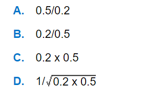
Question

a.
A
b.
B
c.
C
d.
D
Posted under Basic Chemical Engineering
Interact with the Community - Share Your Thoughts
Uncertain About the Answer? Seek Clarification Here.
Understand the Explanation? Include it Here.
Q. An ideal PID controller has the transfer function [1 + 1/0.55 + 0.25 ]. The frequency at which the magnitude ratio of the controller is 1, is
Similar Questions
Explore Relevant Multiple Choice Questions (MCQs)
Q. The unit step response of the following transfer function reaches its final steady state assymptotically after
View solution
Q. A process is initially at steady state with its output y=1 for an input u=1. The input is suddenly changed to 2 at time t=0. The output response is y(t)=1+2t. The transfer function of the process is
View solution
Q. Which of the systems having the following transfer function is stable ?
View solution
Q. The calibration data of a thermocouple with its cold junction at 0°C are given below.
The hot junction of the thermocouple is placed in a bath at 80°C, while its cold junction is at 20°C. What is the emf of thermocouple ?
View solution
Q. The frequency response of a dynamic element shows a constant magnitude ratio at all frequencies. The element exhibits a negative phase shift at all frequencies. The absolute value of the phase shift increases linearly with frequency. The element has the transfer function
View solution
Q. For the block diagram shown below, the characteristic equation is
View solution
Q. The experimental response of the controlled variable y(t) for a step change of magnitude P in the manipulated variable x(t) is shown below.
The appropriate transfer function of the process is
View solution
Q. The open loop transfer function of a process is given below. In the root locus diagram, the poles will be at
View solution
Q. Water is entering a storage tank at a temperature T₀ and flow rate Q₀ and leaving at a flow rate Q and temperature T. There are negligible heat losses in the tank. The area of cross-section of the tank is A₀. The model that describes the dynamic variation of temperature of water in the tank with time is given as :
View solution
Q. The transfer function of a second order system is
View solution
Q. The Laplace transform of a sinusoidal function (eg; sin at) is represented by the curve
View solution
Q. The transfer function of a first order system is
View solution
Q. The transfer function of a pure dead time system with dead time τd is
View solution
Q. Which of following error integral is considered as the best criterion in controller settings ?
View solution
Q. Pick out the symbol for "locally mounted instrument" in instrumentation diagram.
View solution
Q. Block diagram of a simple standard control system is shown below in the figure. Which of the following statement about the above control system is wrong ?
View solution
Q. Water is flowing through a series of four tanks and getting heated as shown in figure. It is desired to design a cascade control scheme for controlling the temperature of water leaving the tank 4 as there is a disturbance in the temperature of a second stream entering the tank 2. Select the best place to take the secondary measurement for the second loop.
View solution
Q. Which is the symbol for "pneumatic control valve" ?
View solution
Q. Find the ultimate gain and frequency for a proportional controller in the case of a process having the transfer function Gp(s) = 1/(4s + 1)(2s + 1)(s + 1).
View solution
Q. Find the Laplace transform of the following input function shown in figure.
View solution
Recommended Subjects
Are you eager to expand your knowledge beyond Basic Chemical Engineering? We've handpicked a range of related categories that you might find intriguing.
Click on the categories below to discover a wealth of MCQs and enrich your understanding of various subjects. Happy exploring!


