Question
a.
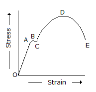
from O to A
b.
from A to C
c.
from A to D
d.
from D to E
Posted under Mechanical Engineering
Interact with the Community - Share Your Thoughts
Uncertain About the Answer? Seek Clarification Here.
Understand the Explanation? Include it Here.
Q. In the below figure, stress is proportional to strain, for the portion
Similar Questions
Explore Relevant Multiple Choice Questions (MCQs)
Q. The state of stress at a point in a loaded member is shown in the below figure. The magnitude of maximum shear stress is
View solution
Q. In the below figure, the plastic range occurs
View solution
Q. In the below figure, Hook's law holds good, for the portion from O to A.
View solution
Q. In the below figure, curve C represents soft brass.
View solution
Q. In the below figure, __________ represents glass.
View solution
Q. A circular shaft fixed at, A has diameter D for half of its length and diameter D/2 over the other half, as shown in the below figure. If the rotation of B relative to A is 0.1 radian, the rotation of C relative to B will be
View solution
Q. For the beam shown in the below figure, the shear force diagram between A and B is
View solution
Q. In the below figure, the point C represents
View solution
Q. The radius of the Mohr 's circle in the given figure is equal to
View solution
Q. In the below figure, the point E represents the maximum stress.
View solution
Q. The given figure shows the Mohr's circle of stress for two unequal and like principal stresses (σx and σy) acting at a body across two mutually perpendicular planes. The normal stress on an oblique section making an angle θ with the minor principle plane is given by
View solution
Q. For the beam shown in the below figure, the shear force at A is equal to
View solution
Q. A ship with jet propulsion draws water through inlet orifices at right angles to the direction of its motion. The propelling force of the jet is (where a = Area of the jet, Vr = Relative velocity of the jet and ship = V + v, v = Velocity of the ship, and V = Velocity of the jet issuing from the ship)
View solution
Q. In a stress-strain diagram as shown in the below figure, the curve A represents
View solution
Q. For a beam, as shown in the below figure, the deflection at C is (where E = Young's modulus for the beam material, and I = Moment of inertia of the beam section. )
View solution
Q. A rectangular beam subjected to a bending moment is shown in the below figure. The upper layer of the beam will be in tension.
View solution
Q. When a body is subjected to a direct tensile stress (σx) in one plane accompanied by a simple shear stress (τxy), the maximum shear stress is
View solution
Q. The maximum bending moment for the beam shown in the below figure, is
View solution
Q. When a body is subjected to a direct tensile stress (σx) in one plane accompanied by a simple shear stress (τxy ), the maximum normal stress is
View solution
Q. The relation between modulus of elasticity (E) and modulus of rigidity (C) is given by
View solution
Recommended Subjects
Are you eager to expand your knowledge beyond Mechanical Engineering? We've handpicked a range of related categories that you might find intriguing.
Click on the categories below to discover a wealth of MCQs and enrich your understanding of various subjects. Happy exploring!