Question
a.
A
b.
B
c.
C
d.
D
Posted under Electronics and Communication Engineering
Interact with the Community - Share Your Thoughts
Uncertain About the Answer? Seek Clarification Here.
Understand the Explanation? Include it Here.
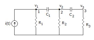
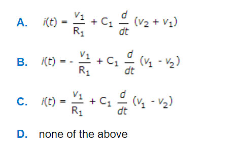
Q. For node 1 in figure, KCL equation is
Similar Questions
Explore Relevant Multiple Choice Questions (MCQs)
Q. In the circuit of figure, the switch is closed at t = 0. At t = 0⁺ the current through C is
View solution
Q. In the figure shown, A1, A2, A3 are identical Ammeters. If A1 and A3 read 5 and 13 A respectively, reading of A2 will be
View solution
Q. An infinite ladder is constructed with 1 Ω and 2 Ω resistors shown below.
View solution
Q. In the circuit of figure the voltage across capacitor when switch is closed at t = ∞ is
View solution
Q. In the series circuit shown in figure, for series resonance, the value of the coupling coefficient, K will be
View solution
Q. The degree of the nodes 1, 2, 3, 4 is
View solution
Q. A series RL circuit has Z(s) = 1/s+4 . If a voltage 4 sint + 4t is applied, the steady state current will be
View solution
Q. The circuit in figure will act as ideal current source with respect to terminals A and B when frequency is
View solution
Q. The time constant of the circuit in figure shown.
View solution
Q. In the circuit shown in given figure, the values of i(0+) and I(∞), will be respectively
View solution
Q. The current wave shape shown in figure (1) is applied to a circuit element. The voltage across the element is shown in figure (2). The element is
View solution
Q. In figure, the current supplied by battery immediately after switching on the circuit is
View solution
Q. In the given circuit, viewed from AB, the circuit can be reduced to an equivalent circuit as
View solution
Q. For the network of figure KVL for first loop is
View solution
Q. In the circuit shown in figure the current I of sinusoidal source is
View solution
Q. In figure the voltage drop across the 10 Ω resistance is 10 V. The resistance R
View solution
Q. An ideal transformer has a turn ratio of 2 : 1. Taking hv side as port 1 and lv side as port 2, transmission parameters of transformer are
View solution
Q. The voltage e0 in the figure
View solution
Q. The distance between the plates of a parallel plate capacitor is d. The dielectric is in two parts, each of equal thickness but dielectric constants ∈1 and ∈2 respectively. The total capacitance will be proportional to
View solution
Q. In figure, the capacitor is charged to 1 V. At t = 0 the switch is closed so that i = e^(-t). When i = 0.37 A, the voltage across capacitor is
View solution
Recommended Subjects
Are you eager to expand your knowledge beyond Electronics and Communication Engineering? We've handpicked a range of related categories that you might find intriguing.
Click on the categories below to discover a wealth of MCQs and enrich your understanding of various subjects. Happy exploring!