Question
a.
1 V
b.
0.63 V
c.
0.37 V
d.
0.185 V
Posted under Electronics and Communication Engineering
Interact with the Community - Share Your Thoughts
Uncertain About the Answer? Seek Clarification Here.
Understand the Explanation? Include it Here.
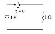
Q. In figure, the capacitor is charged to 1 V. At t = 0 the switch is closed so that i = e^(-t). When i = 0.37 A, the voltage across capacitor is
Similar Questions
Explore Relevant Multiple Choice Questions (MCQs)
Q. The Voltage e0 in the figure,
View solution
Q. Consider the following statement:
View solution
Q. The circuit in figure is switched on at t = 0. At any time t, i(t) =
View solution
Q. A system is at rest for t < 0. It is given by the following equation. If steady state is reached at t = 0, then the value of angle A is given by
View solution
Q. In the circuit of figure the current through C at t = ∞ is
View solution
Q. The average value of the waveform is
View solution
Q. For the circuit in figure, fed by a unit step voltage, vc =
View solution
Q. For the network of figure, z11 =
View solution
Q. In figure
View solution
Q. Figure shows a dc circuit fed by a current source. With respect to terminals AB, Thevenin's voltage and Thevenin's resistance are
View solution
Q. In figure, the value of R should be
View solution
Q. A resistance coil has self inductance L, resistance R and capacitance C. The impedance across the coil is
View solution
Q. In figure, the current iL at t = ∞ is
View solution
Q. In figure, the battery has remained switched on for a long time. At t = 0 the switch is closed. The current i(t) is likely to be
View solution
Q. A resistance R is connected to a voltage source Vs having internal resistance Rs. A voltmeter of resistance Rm is used to measure the voltage across R. The voltmeter will read
View solution
Q. In the circuit shown in figure, for different values of R, the values of V and I are given. Other elements remaining the same. when R = ∞, V = 5 volt
1. R = 0, I = 2.5 A
2. R = 3 Ω, the value of V is given by
View solution
Q. In figure, E = 1 V (rms value). The average power is 250 mW. Then phase angle between E and I is
View solution
Q. Given Is = 20 A, Vs = 20 V, the current I in the 3 Ω resistance is given by
View solution
Q. For the three coupled coils shown in figure, KVL equation is
View solution
Q. Figure shows a dc circuit. The Thevenin's equivalent circuit at terminals a - b is
View solution
Recommended Subjects
Are you eager to expand your knowledge beyond Electronics and Communication Engineering? We've handpicked a range of related categories that you might find intriguing.
Click on the categories below to discover a wealth of MCQs and enrich your understanding of various subjects. Happy exploring!