Question
a.
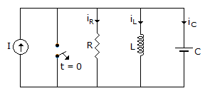
I = iR + iL
b.
I = iR + iL iC
c.
I = iR + iL - iC
d.
I = iR - iL - iC
Posted under Electronics and Communication Engineering
Interact with the Community - Share Your Thoughts
Uncertain About the Answer? Seek Clarification Here.
Understand the Explanation? Include it Here.
Q. In figure which is correct at any time t
Similar Questions
Explore Relevant Multiple Choice Questions (MCQs)
Q. In figure, the magnitude of V
View solution
Q. The driving point impedance of a network is given by following equation. The number of energy storing elements in the network is
View solution
Q. The following differential equation has
View solution
Q. If the transmission parameters of the given networks are A = C = 1, B = 2 and D = 3, then the value of Zm is
View solution
Q. In figure, the current through 10 V battery is
View solution
Q. The switch in figure is initially closed. At t = 0 the switch is opened. At t = 0+, the current through R is
View solution
Q. The power dissipated in 4 Ω resistance in figure is
View solution
Q. In the network of the figure is the maximum power is delivered to RL if its value is
View solution
Q. A two-port network is represented by ABCD parameters given by following equation. If port is terminated by RL, then input impedance seen at port 1 is given by
View solution
Q. In figure, the switch is closed at t = 0. At t = 0+ The value of current supplied by battery is
View solution
Q. In the circuit shown in the figure the power dissipated in 30 Ω resistor will be maximum if the value of R is
View solution
Q. Which of the following polynomials is not Hurwitz?
View solution
Q. In an RLC underdamped circuit
View solution
Q. The time constant of the network shown in figure is
View solution
Q. A T network is inserted between source and R as shown in figure. The resistance seen by the source remains the same with or without T network when R is
View solution
Q. The circuit shown in the figure has initial current iL(0) = 1A through the inductor and an initial voltage vc(0) = 1 V across the capacitor. For input v(t) = U(t) the Laplace transform of the current i(t) for t ≥ 0 is
View solution
Q. In figure, the time constant for the capacitor charging is
View solution
Q. In figure, the short circuit current through terminal AB will be
View solution
Q. The current wave of figure, is passed through a 3 H inductor during the period 0 to 2 seconds
View solution
Q. The minimum number of equations required to analyze the circuit shown in the figure is
View solution
Recommended Subjects
Are you eager to expand your knowledge beyond Electronics and Communication Engineering? We've handpicked a range of related categories that you might find intriguing.
Click on the categories below to discover a wealth of MCQs and enrich your understanding of various subjects. Happy exploring!