Question
a.
5 sin (2t + 53.1°)
b.
5 sin (2t - 53.1°)
c.
25 sin (2t + 53.1°)
d.
25 sin (2t - 53.1°)
Posted under Electronics and Communication Engineering
Interact with the Community - Share Your Thoughts
Uncertain About the Answer? Seek Clarification Here.
Understand the Explanation? Include it Here.
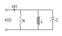
Q. The circuit shown in the figure, with R = 1/3 Ω, L = 1/4H, C = 3F has input voltage v(t) = sin2t. The resulting current i(t) is
Similar Questions
Explore Relevant Multiple Choice Questions (MCQs)
Q. In the circuit of figure. The current supplied by battery at t = ∞ is
View solution
Q. The natural frequency Sn of the given circuit is
View solution
Q. In figure, S is closed at t = 0. At t = t1, I = 1 A and di/dt = 1 A/s. Then the value of L is
View solution
Q. In the circuit of figure, the switch is closed at t = 0. At t = 0+ the current supplied by battery is
View solution
Q. The current in an RL series circuit is 1 - e^(-t) amperes. Then di/dt is
View solution
Q. In the circuit of figure, the current through battery E2 is
View solution
Q. In figure, the current supplied by battery at t = 0.5s is
View solution
Q. In figure, the current through R, after the steady state condition is reached, is
View solution
Q. Special circuits using neon tubes, contact relays and capacitors are used in many domestic appliances. The role of capacitor in figure is to
View solution
Q. In figure, the power associated with 3 A source is
View solution
Q. In the circuit shown in figure the inductor current and capacitor voltage are given at a time t. At this instant i is __________ A and di/dt is __________ A/sec.
View solution
Q. In the circuit of figure the current through 3 Ω resistance at t = ∞ is
View solution
Q. In figure, i(0-) and v(0-) are zero. The switch is closed at t = 0, i(0+) and (∞) are
View solution
Q. The Laplace transforms of voltage function shown in figure is
View solution
Q. In figure, the switch has been closed position for a long time. At t = 0 the switch is opened. At t = 0+, the current ic is
View solution
Q. For the port shown, the short circuit network function at port 2 is given by
View solution
Q. A series RL circuit is initially relaxed. A step voltage is applied to the circuit. If t is the time constant of the circuit, the voltage across R and L will be same at time t equal to
View solution
Q. In figure, the transmission parameters are A = C = 1, B = 2 and D = 3. Then Zin =
View solution
Q. A sinusoidal voltage is written as v = Im (R² + XC²)^0.5 sin 314 t. Its peak value and frequency are
View solution
Q. KVL equation for the circuit of figure is
View solution
Recommended Subjects
Are you eager to expand your knowledge beyond Electronics and Communication Engineering? We've handpicked a range of related categories that you might find intriguing.
Click on the categories below to discover a wealth of MCQs and enrich your understanding of various subjects. Happy exploring!