Question

a.
0.5 Vm
b.
2/3 Vm
c.
0.75 Vm
d.
0.91 Vm
Posted under Electronics and Communication Engineering
Interact with the Community - Share Your Thoughts
Uncertain About the Answer? Seek Clarification Here.
Understand the Explanation? Include it Here.
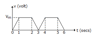
Q. For the wave shown in figure, the average value is
Similar Questions
Explore Relevant Multiple Choice Questions (MCQs)
Q. Consider the following two statements:
View solution
Q. Paley Wiener criterion states that a necessary and sufficient condition for an amplitude function |H(jω)| to be causal is that
View solution
Q. Choose the correct option, where H(s) is transfer function, Z(s) is driving point impedance functions
View solution
Q. In figure, V reads 45V. Then I =
View solution
Q. For the time domain response shown in figure the pole
View solution
Q. A system described by the following differential equation is initially rest for input x(t) = 2 u(t), the output y(t) is
View solution
Q. Consider the following two statements:
View solution
Q. Which one of the following functions is RC driving point impedance?
View solution
Q. For figure, the incidence matrix A is
View solution
Q. The input resistance of the network in figure is
View solution
Q. In the set of equation
View solution
Q. Z-matrix for the network shown in the given figure is
View solution
Q. If Δs is an element of area and ΔI is the current through this element, current density J is defined as
View solution
Q. The Z parameter of the following T-network is
View solution
Q. Laplace transform of tn is
View solution
Q. For graph of figure, one set of fundamental cutsets would be
View solution
Q. The closing of switch S1 and S2 in figure will light up
View solution
Q. In figure, the current through R is 1 A when VA = 0 and VB = 15V. If both VA and VB are increased by 15V each, current through R will be
View solution
Q. In the circuit of figure, the switch is closed at t = 0 with iL (0) = 0 and VC (0) = 0. In the steady state nc equals.
View solution
Q. The maximum power that can be transferred to the load is resistor RL from the voltage source in the figure is
View solution
Recommended Subjects
Are you eager to expand your knowledge beyond Electronics and Communication Engineering? We've handpicked a range of related categories that you might find intriguing.
Click on the categories below to discover a wealth of MCQs and enrich your understanding of various subjects. Happy exploring!


