Question

a.
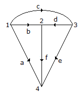
abc, cde, afe
b.
afde, afe, abdc
c.
cbfe, afe, bdf
d.
cbd, adbe, cde
Posted under Electronics and Communication Engineering
Interact with the Community - Share Your Thoughts
Uncertain About the Answer? Seek Clarification Here.
Understand the Explanation? Include it Here.
Q. For graph of figure, one set of fundamental cutsets would be
Similar Questions
Explore Relevant Multiple Choice Questions (MCQs)
Q. The closing of switch S1 and S2 in figure will light up
View solution
Q. In figure, the current through R is 1 A when VA = 0 and VB = 15V. If both VA and VB are increased by 15V each, current through R will be
View solution
Q. In the circuit of figure, the switch is closed at t = 0 with iL (0) = 0 and VC (0) = 0. In the steady state nc equals.
View solution
Q. The maximum power that can be transferred to the load is resistor RL from the voltage source in the figure is
View solution
Q. The Thevenin equivalent circuit to the left of AB has Req
View solution
Q. The RLC circuit for driving point following admittance function is
View solution
Q. The following function is
View solution
Q. In figure, the ratio V24/V23 is
View solution
Q. The pass band of a constant k filter with Z1 and Z2 as series and shunt arm impedances is given by
View solution
Q. Which one is correct option, if initial conditions is not zero, for inductor (L) and capacitor (c) is
View solution
Q. The current density J at a point and current I are related as
View solution
Q. For an ac circuit having capacitance C, instantaneous current i and instantaneous voltage e are related as
View solution
Q. In figure the total inductance of the circuit is
View solution
Q. In figure, the effective capacitance between A and B is
View solution
Q. If Va1, Va2, Va0 are the symmetrical components of Va, then
View solution
Q. A Two port network has V1 = 24 I1 + 8 I2 and V2 = 8 I1 + 32 I2 which of the following networks is represented by above equation?
View solution
Q. If f(t) = r (t - a), F(s) =
View solution
Q. For the network in figure, which of the following expressions gives the value of net inductance between terminals A and B
1. L1 ± L2
2. L1 ± L2 ± M
3. L1 ± L2 - 2M
4. L1 ± L2 ± 2M
Select the answer using the following codes
View solution
Q. The parallel RLC circuit shown in figure is in resonance. If
View solution
Q. Load ZL for maximum power transfer is
View solution
Recommended Subjects
Are you eager to expand your knowledge beyond Electronics and Communication Engineering? We've handpicked a range of related categories that you might find intriguing.
Click on the categories below to discover a wealth of MCQs and enrich your understanding of various subjects. Happy exploring!


