Question
a.
1/2
b.
1/3
c.
1/6
d.
1/12
Posted under Electronics and Communication Engineering
Interact with the Community - Share Your Thoughts
Uncertain About the Answer? Seek Clarification Here.
Understand the Explanation? Include it Here.
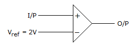
Q. If the input to the ideal comparator shown in the figure is a sinusoidal signal of 8 V (peak to peak) without any DC component, then the output of the comparator has a duty cycle...
Similar Questions
Explore Relevant Multiple Choice Questions (MCQs)
Q. A half wave diode circuit using ideal diode has an input voltage 20 sin ωt volts. Then average and rms values of output voltage are
View solution
Q. In figure v1 = 8 V and v2 = 4 V. Which diode will conduct?
View solution
Q. Gain of the amplifier is 'A'. Then the I/P impedance and O/P impedance of the closed loop amplifier shown below would be
View solution
Q. In figure The minimum and maximum load currents are
View solution
Q. In figure, VEB = 0.6 V, β = 99. Then VC and IC are
View solution
Q. The input impedance of op-amp circuit of figure is
View solution
Q. The output V0 in figure is
View solution
Q. The transistor of following figure in Si diode with a base current of 40 μA and ICBO = 0, if VBB = 6V, RE = 2 kΩ and β = 90, IBQ = 20 μA then RB =
View solution
Q. In the amplifier circuit of figure hfe = 100 and hie = 1000 Ω. The voltage gain of amplifier is about
View solution
Q. In figure what is the base current if VBE = 0.7 V
View solution
Q. In figure ID = 4 mA. Then VS =
View solution
Q. In figure what is value of IC if βdc = 100. Neglect VBE
View solution
Q. In figure the saturation collector current is
View solution
Q. In figure v1 = 8 V and v2 = 8 V. Which diode will conduct?
View solution
Q. Si transistor of following figure has a = 0.9 and ICE= 0, VEE = 5 V and VCC = 13 V, then RE will be if IEQ = 1 mA
View solution
Q. The 'h' parameters of the circuit shown in the figure are hib = 25 Ω, hfb = 0.999 and hob = 10¯⁶Ω The Voltage gain is
View solution
Q. Study the circuit of figure and examine the following statements:
1. It is an active low pass finer.
2. It is a second order filter.
3. The change in gain is 40 dB/decade.
Which of the above statements are correct?
View solution
Q. In a circuit of figure, Vs = 10 cos(ωt) power drawn by the 2Ω resistor is 4 watts. The power factor is
View solution
Q. In the op-amp circuit of figure, V0 =
View solution
Q. Figure shows the self bias circuit for CE amplifier and its equivalent circuit. VBB and RB respectively are
View solution
Recommended Subjects
Are you eager to expand your knowledge beyond Electronics and Communication Engineering? We've handpicked a range of related categories that you might find intriguing.
Click on the categories below to discover a wealth of MCQs and enrich your understanding of various subjects. Happy exploring!