Question
a.
23.7 mA
b.
14.2 mA
c.
13.7 mA
d.
24.2 mA
Posted under Electronics and Communication Engineering
Interact with the Community - Share Your Thoughts
Uncertain About the Answer? Seek Clarification Here.
Understand the Explanation? Include it Here.
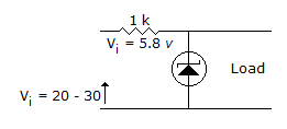
Q. The zener diode in the rectangular circuit shown in the figure has a zener voltage of 5.8 volts and a zener knee current of 0.5 mA. The maximum load current drawn from this circuit...
Similar Questions
Explore Relevant Multiple Choice Questions (MCQs)
Q. In figure, ID = 4 mA. Then VDS =
View solution
Q. In figure, V0 =
View solution
Q. In the circuit of figure diode will conduct
View solution
Q. In figure, V0 =
View solution
Q. The JFET in the circuit shown in figure has an IDSS = 10 mA and Vp = -5V. The value of the resistance Rs for a drain current IDS = 6.4 mA is
View solution
Q. In figure, V0 =
View solution
Q. In the op-amp circuit of figure, V0 =
View solution
Q. In figure the zener has a resistance of 5 ohms. As the load resistance is varied, the output voltage
View solution
Q. The transistor of following figure in Si diode with a base current of 40 μA and ICBO = 0, if VBB = 6V, RE = 2 kΩ and β = 90, IBQ = 20 μA then IEQ =
View solution
Q. In the CE circuit shown in figure the slope of ac load line will be
View solution
Q. The op-amp circuit shown in the figure is a filter. The type of filter and its cut off type of filter and its cut off frequency are respectively.
View solution
Q. In the circuit of figure, PIV can be up to
View solution
Q. In the circuit of figure β = 50 and VBE = 0.5 V. The quiescent value of base current IB is
View solution
Q. In figure the input and output Miller capacitances are
View solution
Q. Figure uses 10 V zener diode. The minimum and maximum current through series resistance are
View solution
Q. When Z1 << Z, The circuit of figure works as
View solution
Q. Voltage VL in the circuit when Vs < 0 where D is an ideal diode. (Take R1 = Rs = RL = 1 Ω)
View solution
Q. For the amplifier in figure, β = 800. The mid-band voltage gain V0/Vi is
View solution
Q. In the circuit of figure, v0 =
View solution
Q. The bandwidth of an amplifier is BW, of n-stage of such as amplifier are cascaded, the bandwidth will become
View solution
Recommended Subjects
Are you eager to expand your knowledge beyond Electronics and Communication Engineering? We've handpicked a range of related categories that you might find intriguing.
Click on the categories below to discover a wealth of MCQs and enrich your understanding of various subjects. Happy exploring!