Question
a.
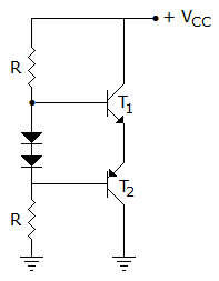
the collector currents of T1 and T2 are equal
b.
the collector current of T1 is more than that of T2
c.
the collector current of T1 is double that of T2
d.
the collector currents of T2 is more than that of T1
Posted under Electronics and Communication Engineering
Interact with the Community - Share Your Thoughts
Uncertain About the Answer? Seek Clarification Here.
Understand the Explanation? Include it Here.
Q. In figure
Similar Questions
Explore Relevant Multiple Choice Questions (MCQs)
Q. In a Hartley oscillator the condition for sustained oscillations is hfe = L₁/L₂ . If there exists mutual inductance M between coils L₁ and L₂, then the above condition will get modified as hfe
View solution
Q. Figure shows current pulses of a class C power amplifier. The fundamental frequency of these pulses is
View solution
Q. The Clapp oscillator shown in figure will operate at
View solution
Q. Figure shows a zener circuit and characteristic of the zener used. If R2 is the lowest load resistance, then for proper voltage regulation R1 must be
View solution
Q. In figure, VC is approximately equal to
View solution
Q. Figure shows small signal model of CB amplifier circuit. Then I and R are respectively equal to
View solution
Q. Figure represents a
View solution
Q. In figure VBE = 0.7 V. If base current required to saturate the transistor is 0.1 mA, Vi =
View solution
Q. As per miller theorem the circuit of figure (1) can be replaced by that in figure (2) If V1/V2 = K, then Y1 and Y2 are equal to
View solution
Q. In a biased JFET (Figure) the shape of the channel is as shown because
View solution
Q. In a half wave rectifier, Vrms is
View solution
Q. The approximate value of input impedance of a common emitter amplifier with emitter resistance Re is given by
View solution
Q. The collector voltage VC of the circuit shown in the given figure aside is approximately
View solution
Q. The symbol shown in figure represents a
View solution
Q. Which of the following represents the equivalent circuit of a crystal for crystal oscillator?
View solution
Q. In figure, the function of resistor R is
View solution
Q. The circuit of figure is
View solution
Q. In figure output impedance of amplifier is
View solution
Q. In figure VCEQ for each transistor is
View solution
Q. A multistage amplifier has a low pass response with three real poles at s = - w1 - w2 and w3. The approximate overall bandwidth B of the amplifier will be given by
View solution
Recommended Subjects
Are you eager to expand your knowledge beyond Electronics and Communication Engineering? We've handpicked a range of related categories that you might find intriguing.
Click on the categories below to discover a wealth of MCQs and enrich your understanding of various subjects. Happy exploring!