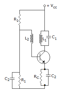
Question
a.
negative resistance oscillators
b.
tuned base tuned collector oscillators
c.
relaxation oscillators
d.
L-C tuned oscillators
Posted under Electronics and Communication Engineering
Interact with the Community - Share Your Thoughts
Uncertain About the Answer? Seek Clarification Here.
Understand the Explanation? Include it Here.
Q. Sweep voltage generators, sweep current generators, multivibrators and blocking oscillators can be combined as
Similar Questions
Explore Relevant Multiple Choice Questions (MCQs)
Q. The configuration of figure is a
View solution
Q. Oscillation frequency in colpitt's oscillator is
View solution
Q. In the case of the circuit shown in the figure Vio = 10 mV dc maximum, the maximum possible output offset voltage Voo caused by the input offset voltage Vio with respect to ground is
View solution
Q. For a sinusoidal input, the circuit shown in the figure will act as a
View solution
Q. The circuit of figure is called
View solution
Q. In figure the potential of gate terminal is
View solution
Q. A distorted sinusoidal has the amplitudes A1, A2, A3 ... of the fundamental, second, harmonic third harmonic, ... respectively. The total harmonic distortion is
View solution
Q. In figure the coordinates of Q point on the load line are (Neglect VBE)
View solution
Q. In the re model of a BJT amplifier, the ac resistance of diode at room temperature is about (IE is quiescent emitter current)
View solution
Q. Symbol shown in figure represents a
View solution
Q. Figure shows basic Hartley oscillator configuration. Do you think the polarities marked for the split coiled are correct?
View solution
Q. In the case of the circuit shown in the figure, the collector current IC will be, if β = 100, VBE = 0.7 V, ICO = 0.1 βA at 20°C
View solution
Q. The circuit of figure is
View solution
Q. In figure VCE (sat) = 0.1 V. Then IC (sat) =
View solution
Q. The circuit shown in figure will
View solution
Q. For the circuit shown in the figure, the capacitor C is initially uncharged. At t = 0, the switch S is closed. The voltage Vc across the capacitor at t = 1 millisecond is (In the figure shown above, the op-amp is supplied with ± 15 V and the ground has been shown by the symbol)
View solution
Q. In figure, D2 turns on when
View solution
Q. Figure shows the feedback network of one of the very popular types of sinusoidal oscillators. Which one is that?
View solution
Q. In figure the trace on the CRO will be
View solution
Q. The circuit shown I/P in the figure represents
View solution
Recommended Subjects
Are you eager to expand your knowledge beyond Electronics and Communication Engineering? We've handpicked a range of related categories that you might find intriguing.
Click on the categories below to discover a wealth of MCQs and enrich your understanding of various subjects. Happy exploring!