Question

a.
lag compensator
b.
lead compensator
c.
lag-lead compensator
d.
none of the above
Posted under Electronics and Communication Engineering
Interact with the Community - Share Your Thoughts
Uncertain About the Answer? Seek Clarification Here.
Understand the Explanation? Include it Here.
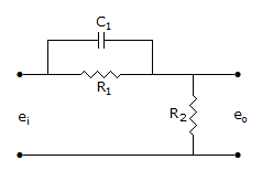
Q. The compensator of the given figure is a
Similar Questions
Explore Relevant Multiple Choice Questions (MCQs)
Q. If error voltage is e(t), integral square error =
View solution
Q. In the given figure the input is x(t) = A sin ωt. The steady state output y(t) =
View solution
Q. In the given figure x6 =
View solution
Q. For the given figure, C(s)/R(s) =
View solution
Q. For the control system in the given figure, the value of K for critical damping is
View solution
Q. For the system in the given figure, C(s)/R(s) =
View solution
Q. In the given figure, if R = XC, voltage gain is
View solution
Q. For the circuit in the given figure, V2(s)/V1(s) =
View solution
Q. The system in the given figure, has
View solution
Q. The given figure shows a pole zero diagram. The transfer function G(j1) is
View solution
Q. For very low frequencies, v0/vi in the given figure equals
View solution
Q. For the system of the given figure the transfer function is
View solution
Q. The first column of a Routh array is given below. How many roots of the corresponding characteristic equation are in left half s-plane?
View solution
Q. For the given figure, time constant RC = t. Then Vo(s)/Vi(s) =
View solution
Q. In the given figure, C(s) =
View solution
Q. For G(jω) =
View solution
Q. The transient response of a second order system is given by following equation. For 5% criterion the settling time is
View solution
Q. For the system in the given figure, the transfer function C(s)/R(s) is
View solution
Q. For the system in the given figure, the characteristic equation is
View solution
Q. In the given figure the transfer function C(s)/N(s) =
View solution
Recommended Subjects
Are you eager to expand your knowledge beyond Electronics and Communication Engineering? We've handpicked a range of related categories that you might find intriguing.
Click on the categories below to discover a wealth of MCQs and enrich your understanding of various subjects. Happy exploring!


