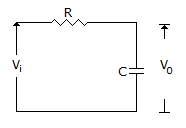
Question

a.
0 dB
b.
3 dB
c.
-3 dB
d.
-20 dB
Posted under Electronics and Communication Engineering
Interact with the Community - Share Your Thoughts
Uncertain About the Answer? Seek Clarification Here.
Understand the Explanation? Include it Here.
Q. In the given figure the input frequency f = 10(1/2 π RC)
Similar Questions
Explore Relevant Multiple Choice Questions (MCQs)
Q. For the second order system given by following equation, damping ratio is
View solution
Q. In the given figure, P = 3 kg force. Then X(s) =
View solution
Q. The polar plot in the given figure is for the term
View solution
Q. The compensator in the given figure is a
View solution
Q. For the block diagram of the given figure, the equation describing system dynamics is
View solution
Q. For the given figure C(s)/R(s)
View solution
Q. The polar plot of
View solution
Q. For the system of the given figure, the undamped natural frequency of closed loop poles is
View solution
Q. In the given figure C(s)/U(s) =
View solution
Q. The signal flow graph of a system is shown in the given figure. The effect of disturbance TD can be reduced by
View solution
Q. A motor is coupled to a load through gear ratio n. If T is the motor torque, Jm and JL are moment of inertia of rotor and load, then torque to inertia ratio referred to motor shaft is
View solution
Q. In the given figure the input frequency f = 0.1 (1/2 π RC)
View solution
Q. The open loop frequency response of a unity feed back system is as given below. The gain margin and phase margin respectively are
View solution
Q. The following transfer function can be for
View solution
Q. In response to a unit step input the controller output in given figure is for
View solution
Q. Given figure shows the magnitude plot for a system. The steady state error for unit step input is
View solution
Q. For very low frequencies, log magnitude for the given figure is
View solution
Q. In the given figure, P = Pm sin ωt. Then X(s) =
View solution
Q. The given figure shows three Nyquist plots of G(s) H(s) = e^(-sT)/[s(s + 1)] for different values of T. The curves 1, 2, 3 can be
View solution
Q. The system in the given figure
View solution
Recommended Subjects
Are you eager to expand your knowledge beyond Electronics and Communication Engineering? We've handpicked a range of related categories that you might find intriguing.
Click on the categories below to discover a wealth of MCQs and enrich your understanding of various subjects. Happy exploring!


