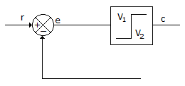
Question

a.
On-off controller
b.
On-off controller with differential gap
c.
On-off controller with integral gap
d.
Three position controller
Posted under Electronics and Communication Engineering
Interact with the Community - Share Your Thoughts
Uncertain About the Answer? Seek Clarification Here.
Understand the Explanation? Include it Here.
Q. The block diagram of the given figure for
Similar Questions
Explore Relevant Multiple Choice Questions (MCQs)
Q. The radius and centre of M circles are given by
View solution
Q. For the system in the given figure the root locus
View solution
Q. A system has two poles as shown in the given figure. The zeros are at infinity. If input is unit step, the steady state output is
View solution
Q. A unity feedback system has the following open loop frequency response. The gain margin and phase margin are
View solution
Q. For the system in the given figure, the gain margin is
View solution
Q. In the signal flow graph in the given figure the number of forward paths and pairs of non-touching loops are respectively
View solution
Q. In an armature controlled dc motor let J be equivalent moment of inertia of motor and load, f0 be equivalent viscous friction coefficient of motor and load and θ be angular displacement of motor shaft. Then torque equation is
View solution
Q. Consider the following statement:
View solution
Q. The system of the given figure
View solution
Q. For a feedback system given below, the velocity error constant Kv is given by
View solution
Q. If G(s)H(s) is given by following equation, the closed loop pole will be located at s = -12 when K =
View solution
Q. In the given figure, the combinations of two non touching loops is
View solution
Q. For the system in the given figure G varies slightly, the ratio of open loop sensitivity to closed loop sensitivity is
View solution
Q. The loop transfer function of a feedback system is given below. The number of asymptotes of its root loci are
View solution
Q. Consider the following statements:
View solution
Q. For a closed loop system given below. The imaginary axis intercept of the root loci will be
View solution
Q. The polar plot of
View solution
Q. A FET is a __________ controlled device whereas a bipolar transistor is a __________ controlled device.
View solution
Q. In Bode diagram (log magnitude plot) the factor 1/jω in the transfer function gives a line having slope
View solution
Q. A negative feedback system has G(s) = 1/(s+1) and H(s) = K/s(s+2). The closed loop system is stable for
View solution
Recommended Subjects
Are you eager to expand your knowledge beyond Electronics and Communication Engineering? We've handpicked a range of related categories that you might find intriguing.
Click on the categories below to discover a wealth of MCQs and enrich your understanding of various subjects. Happy exploring!


