Question
a.
A
b.
B
c.
C
d.
D
Posted under Electronics and Communication Engineering
Interact with the Community - Share Your Thoughts
Uncertain About the Answer? Seek Clarification Here.
Understand the Explanation? Include it Here.
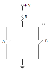
Q. In the switching circuit, switches A, B have value 0 for OFF, 1 for ON and the output Y has 0 volts for 1 volts, then the expression for Y is
Similar Questions
Explore Relevant Multiple Choice Questions (MCQs)
Q. The output Y of the circuit shown in the figure is
View solution
Q. What is the result for following expression (map method)?
View solution
Q. The MOS symbols shown indicates:
1. that it is depletion type
2. that it is enhancement type
3. that it is n channel
4. that it is p channel
5. that electrons flow from D to S
6. that holes flow from D to S
The only true statements are
View solution
Q. For the logic circuit of the given figure the simplified Boolean expression is
View solution
Q. The characteristic equation of flip-flop gives the next state QN + 1 in terms of present state QN and the inputs. Which one of the following is the characteristic equation of J - K flip-flop?
View solution
Q. The characteristic equation for the next state (Qn+1) of a J-K flip-flop is
View solution
Q. Symbol in the given figure is IEEE symbol for
View solution
Q. For the logic circuit of the given figure, Y =
View solution
Q. The circuit realizes the function
View solution
Q. Which of the following is coincidence logic circuit?
View solution
Q. The circuit of the given figure performs
View solution
Q. Figure given below shows the internal schematic of a TTL AND-OR Invert (AOI) gate, For the input shown in the given figure, the output Y is
View solution
Q. The circuit show in the figure has 4 boxes each described by inputs P, Q, R and outputs y, z with
Y = P Ꚛ Q Ꚛ R, Z = RQ + P̅R + QP̅. The circuit act as a
View solution
Q. The MOS symbol shown indicates that
1. It is depletion type
2. It is enhancement type
3. It is channel
4. It is P-channel
5. Electrons flow from s to D
6. Holes flow from D to s
The true statements are
View solution
Q. For the K map of the given figure the simplified Boolean expression is
View solution
Q. The characteristic equation of an SR flip-flop in given by
View solution
Q. For the following decimal multiplication the result are given in binary numbers, Spot the incorrect relation, if any
View solution
Q. In the DRAM cell in the figure is the Vt of the NMOSFET is 1 V. For the following three combinations of WL and BL voltages.
View solution
Q. The circuit in the given figure is
View solution
Q. The output of the circuit shown below will be of the frequency
View solution
Recommended Subjects
Are you eager to expand your knowledge beyond Electronics and Communication Engineering? We've handpicked a range of related categories that you might find intriguing.
Click on the categories below to discover a wealth of MCQs and enrich your understanding of various subjects. Happy exploring!