Question
a.
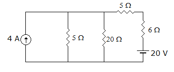
a voltage source of 20 V in series with 5 ohm resistance
b.
a voltage source of 16 V in series with 4 ohm resistance
c.
a voltage source of 20 V in series with 4 Ω resistance
d.
a voltage source of 16 V in series with 5 Ω resistance
Posted under Electronics and Communication Engineering
Interact with the Community - Share Your Thoughts
Uncertain About the Answer? Seek Clarification Here.
Understand the Explanation? Include it Here.
Q. The current source in figure, can be replaced by
Similar Questions
Explore Relevant Multiple Choice Questions (MCQs)
Q. In figure, iL at t = 0+ is
View solution
Q. In the circuit of figure the voltage across C at t = 0+ is
View solution
Q. In the circuit of figure, the power consumed in resistance R is measured when one source is acting at one time. These values are 18 W, 50 W and 98 W. When all source act together the maximum and minimum power can be
View solution
Q. The resistance RAB in the circuit is
View solution
Q. In the circuit of figure the current through L at t = ∞ is
View solution
Q. Current having waveform in figure flows through 10 Ω resistance. Average power is
View solution
Q. S is closed for a long time and steady state is reached. S is opened at t(0-). The voltage marked V is V0 at t = 0+ and Vf at t = ∞. Then value of V0 and Vf are respectively
View solution
Q. The switch in figure is initially closed. At t = 0 the switch is opened. At t = 0+, the current through inductance is
View solution
Q. The resonant frequency of the circuit shown in figure is
View solution
Q. For the circuit shown in the figure, the time constant RC = 1 ms. The input voltage is V1(t) = √2 sin 10³ t. The output voltage V0(t) is equal to
View solution
Q. Flux linkages ψ and voltages v are related as
View solution
Q. Calculate i(t) for t ≥ 0, assuming the switch has been in position A for a long time at t = 0, the switch is moved to position B
View solution
Q. In figure, capacitor is uncharged. The switch is closed at t = 0 at t = 0+ di/dt is
View solution
Q. In figure the total inductance of the circuit is
View solution
Q. In the network of figure, the voltage drops across R1, R2, R3 are 6 V, 8 V and 12 V with polarities as shown. The value of R3 is
View solution
Q. In figure which is correct at any time t
View solution
Q. In figure, the magnitude of V
View solution
Q. The driving point impedance of a network is given by following equation. The number of energy storing elements in the network is
View solution
Q. The following differential equation has
View solution
Q. If the transmission parameters of the given networks are A = C = 1, B = 2 and D = 3, then the value of Zm is
View solution
Recommended Subjects
Are you eager to expand your knowledge beyond Electronics and Communication Engineering? We've handpicked a range of related categories that you might find intriguing.
Click on the categories below to discover a wealth of MCQs and enrich your understanding of various subjects. Happy exploring!