Question
a.
40 V
b.
30 V
c.
20 V
d.
10 V
Posted under Electronics and Communication Engineering
Interact with the Community - Share Your Thoughts
Uncertain About the Answer? Seek Clarification Here.
Understand the Explanation? Include it Here.
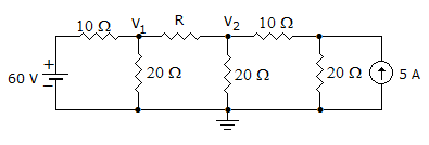
Q. In the figure circuit, V1 = 40 V. When R is 10 Ω. When R is zero, the value of V2 will be
Similar Questions
Explore Relevant Multiple Choice Questions (MCQs)
Q. The Thevenin Resistance of the circuit is
View solution
Q. In the circuit shown in the given figure, RL will absorb maximum power when its value is
View solution
Q. The circuit in figure has reached steady values with switch open. If switch is closed at t = 0 the voltage across 2 μF capacitance at t = 0+ is
View solution
Q. In the circuit of figure
View solution
Q. In a conductor, voltage v, conductance G and charges q are related as
View solution
Q. The current wave in figure is passed through 3 H inductor. The voltage across inductance during the period 2 < t < 3 seconds is
View solution
Q. In figure, the charge on 0.8 μF capacitor is
View solution
Q. In figure, the switch is closed at t = 0 when current through inductor is 6 A, the rate of change of current through resistor is 6 A/s. The value of L is
View solution
Q. In figure, the switch is closed at t = 0. At t = 0+, di/dt = 4 A/s. Then V =
View solution
Q. In figure V is ideal voltmeter having infinite resistance. It will read __________ volt.
View solution
Q. The equivalent inductance seen at terminals A - B is
View solution
Q. For the R-L circuit shown in the figure, the input voltage vi(t) = U(t). The current i(t) is
View solution
Q. A parallel plate capacitor has plate area A and distance between the plates is d. It has two dielectrics each of thickness d and area 0.5 A. The dielectric constants are ∈1 and ∈2. The total capacitance is given by the equation
View solution
Q. Which of the following theorems can be conveniently used to find power consumed in 10 Ω resistor in figure?
View solution
Q. In the circuit of figure is
View solution
Q. The VTH at terminals A and B is equal to
View solution
Q. The circuit in figure, the switched on at t = 0. After a long time the current through 5 Ω resistance is
View solution
Q. In the circuit of figure the current through 5 Ω resistance at t = ∞ is
View solution
Q. In an infinite ladder Ckt as shown above each resistance of rΩ then RAB
View solution
Q. The admittance parameter Y12 in the 2 port network in the figure
View solution
Recommended Subjects
Are you eager to expand your knowledge beyond Electronics and Communication Engineering? We've handpicked a range of related categories that you might find intriguing.
Click on the categories below to discover a wealth of MCQs and enrich your understanding of various subjects. Happy exploring!