Question
a.
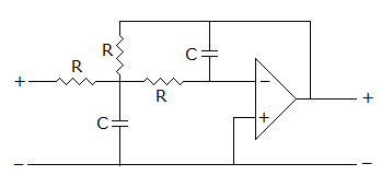
low pass filter
b.
high pass filter
c.
band pass filter
d.
band stop filter
Posted under Electronics and Communication Engineering
Interact with the Community - Share Your Thoughts
Uncertain About the Answer? Seek Clarification Here.
Understand the Explanation? Include it Here.
Q. The filter in figure, uses ideal op-amp. It is
Similar Questions
Explore Relevant Multiple Choice Questions (MCQs)
Q. For a rectified sinusoidal wave clipped at 0.707 its peak value (figure), the average value is
View solution
Q. Figure shows an R-L circuit. The current is i = 1 - e^(-t). The rate of change of current at t = 1 second is
View solution
Q. The time constant of the circuit after the switch shown in the figure is opened is
View solution
Q. Two passive elements are connected in series and a dc voltage is applied to the circuit. The time variation of the current is shown in figure. The two elements are
View solution
Q. The equivalent resistance between terminals x and y figure
View solution
Q. Find Vth in the circuit
View solution
Q. The equivalent inductance measured between the terminals 1 and 2 for the circuit shown in the figure is
View solution
Q. In the circuit, S was initially open. At time t = 0, S is closed. When the current through the inductor is 6 A, the rate of change of current through the resistor is 6 A/s. The value of the inductor would be
View solution
Q. If V = 4 in the figure, the value of Is is given by
View solution
Q. The voltage of the source in circuit shown __________ if i(t) = - 20e^(-2t) is
View solution
Q. The Gaussian filter characteristic figure is realizable.
View solution
Q. The circuit is figure, is in steady state with switch closed. At t = 0 switch is opened. The current i is
View solution
Q. In the circuit shown, the steady state is reached with S open S is closed at t = 0, the current I in the 1 Ω resistor connected is to be determined at t = 0+ is given by
View solution
Q. In figure, VAB =
View solution
Q. In figure, the effective resistance across AB is
View solution
Q. For the wave shown in figure, the average value is
View solution
Q. The dc voltage applied to an R-L series circuit is suddenly changed from V1 to V2. The expression for transient current is
View solution
Q. For the following circuit a source of V1(t) = e^(-2t) is applied, then the resulting response V2(t) is given by
View solution
Q. In figure, the current I4 is
View solution
Q. For the circuit shown in the figure, the current I is
View solution
Recommended Subjects
Are you eager to expand your knowledge beyond Electronics and Communication Engineering? We've handpicked a range of related categories that you might find intriguing.
Click on the categories below to discover a wealth of MCQs and enrich your understanding of various subjects. Happy exploring!