Question
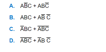
a.
A
b.
B
c.
C
d.
D
Posted under Electronics and Communication Engineering
Interact with the Community - Share Your Thoughts
Uncertain About the Answer? Seek Clarification Here.
Understand the Explanation? Include it Here.
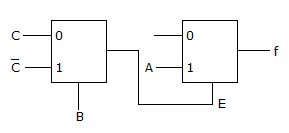
Q. The Boolean function/implemented in the figure using two I/P multiplexers is
Similar Questions
Explore Relevant Multiple Choice Questions (MCQs)
Q. For the logic circuit of the given figure the simplified Boolean equation
View solution
Q. In the given figure RC = RL = 1 kΩ, then V0 =
View solution
Q. Inputs A and B of the given figure are applied to a NAND gate. The output is LOW
View solution
Q. For the NMOS gate in the given figure, F =
View solution
Q. The logic circuit of the given figure is equivalent to
View solution
Q. In the given figure shows a logic circuit. The minimum Boolean expression for this circuit is
View solution
Q. The counter shown in the given figure is built using 4 -ve edge triggered toggle FFs. The FF can be set asynchronously when R = 0. The combinational logic required to realize a modulo-13 counter is
View solution
Q. In the figure, the LED
View solution
Q. Four inputs A, B, C, D are fed to a NOR gate. The output of NOR gate is fed to an inverter. The output of inverter is
View solution
Q. The circuit in the figure is has two CMOS-NOR gates. This circuit functions as a
View solution
Q. In the TTL circuit in the figure, S₂ to S₀ are select lines and X₇ to X₀ are input lines. S₀ and X₀ are LSBs. The output Y is
View solution
Q. The Boolean expression for the shaded area in the Venn diagram is
View solution
Q. The logic realized by the circuit shown in figure below is
View solution
Q. The inputs A and B of the given figure are applied to a two input NOR gate. The output waveform is
View solution
Q. In the circuit of the given figure, V₀ =
View solution
Q. In following figure, the initial contents of the 4-bit serial in parallel out, right shift, shift register as shown in figure are 0110. After 3 clock pulses the contents of the shift register will be
View solution
Q. For the logic circuit of the given figure, the minimized expression is
View solution
Q. The inputs to a NAND gate are as shown in the given figure. The waveform of output is
View solution
Q. In the given figure A = 1, B = 1. B is now changed to a sequence 101010................The outputs X and Y will be
View solution
Q. In 8085 microprocessor, what are the contents of register SP, after the interrupt has been started?
View solution
Recommended Subjects
Are you eager to expand your knowledge beyond Electronics and Communication Engineering? We've handpicked a range of related categories that you might find intriguing.
Click on the categories below to discover a wealth of MCQs and enrich your understanding of various subjects. Happy exploring!