Question
a.
the zener current remain constant
b.
the load current remains constant
c.
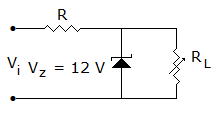
the output voltage remains constant
d.
the output voltage and current through R remain constant
Posted under Electronics and Communication Engineering
Interact with the Community - Share Your Thoughts
Uncertain About the Answer? Seek Clarification Here.
Understand the Explanation? Include it Here.
Q. In figure as the load resistance is changed
Similar Questions
Explore Relevant Multiple Choice Questions (MCQs)
Q. In figure, voltage across R2 = + 10 V. If VBE = 0.7 V and VE = 0.7 V and RE = 10 kΩ, current through RE is
View solution
Q. In figure, transistor βdc = 100 and LED voltage when it is conducting is 2 V. Then the base current which saturates the transistor is
View solution
Q. In figure the dc emitter current of each transistor is about
View solution
Q. Assume that op-amp in figure is ideal. If input Vi is triangular, the output V0 will be
View solution
Q. In the diode circuit of figure the diodes are ideal. The average current through ammeter is
View solution
Q. The critical frequency of the circuit of figure is
View solution
Q. Find resistance RB to bring transistor to threshold of saturation VCB = 0, VBE = 0.7 V, a = 0.96
View solution
Q. In figure ID = 4 mA. Then VGS =
View solution
Q. In following circuit, RB will be if VCC = 10 V, VS = 2 V, RC = 5 kΩ, RS = 90 kΩ, β = 50, ICE = 0, VCEsat = 0.1 V
View solution
Q. In following figure, what will be R1 and R2 for maximum symmetrical swing if VCSat ≈ 0. Given that RE = 200 Ω, RC = 400 Ω, VCC = 20 V, β = 99
View solution
Q. Assertion (A): The circuit in figure produces repetitive narrow pulses when input is fed with sine or triangular waveform having peak value more than + V
Reason (R): The high gain op-amp produces voltages at two levels. If input is more than + V, the output is + 15 V otherwise the output is - 15 V.
View solution
Q. For CE amplifier of figure, the slope of ac load line is
View solution
Q. A non-inverting op-amp summer is shown in figure, the output voltage V0 is
View solution
Q. In figure if C is replaced by short circuit then RB will be
View solution
Q. In the circuit figure LED will be on when v1 is
View solution
Q. Figure shows a portion of linear v - i characteristics of diode. If applied voltage is + 6 V, the current will be
View solution
Q. In figure the zener current
View solution
Q. In the circuit of figure the diode
View solution
Q. In the circuit of figure, v1 = v2 = 10 V. Then
View solution
Q. The inverting op-amp shown in the figure has an open loop gain to 100. The closed loop given Vo/Vs is
View solution
Recommended Subjects
Are you eager to expand your knowledge beyond Electronics and Communication Engineering? We've handpicked a range of related categories that you might find intriguing.
Click on the categories below to discover a wealth of MCQs and enrich your understanding of various subjects. Happy exploring!