Question
a.
A
b.
B
c.
C
d.
D
Posted under Electronics and Communication Engineering
Interact with the Community - Share Your Thoughts
Uncertain About the Answer? Seek Clarification Here.
Understand the Explanation? Include it Here.
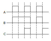
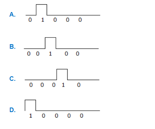
Q. Figure shows three pulse train inputs to a 3-input AND gate. Assuming positive logic, the output signal obtained in figure would be
Similar Questions
Explore Relevant Multiple Choice Questions (MCQs)
Q. A 12-bit binary counter has the following state. The octal number represented is
View solution
Q. For the K map of the given figure the simplified Boolean expression is
View solution
Q. A clock pulse is fed into 3 bit binary down count. The signal at B output is
View solution
Q. The boolean expression for shaded area in the given figure is
View solution
Q. The given figure shows a K-map for a Boolean function. The number of essential prime implicants is
View solution
Q. For the logic circuit given, what is the simplified Boolean function?
View solution
Q. The accuracy of A/D conversion is generally
View solution
Q. Consider the following statements in connection with CMOS inverter in figure where both the MOSFET are of enhancement type and both have a threshold voltage of 2 V
statements 1: T1 conducts when vi ≥ 2 V
statements 2: T1 is always in saturation when v0 = 0 V
Which of the following is correct?
View solution
Q. In number system e.g. 6, a “decade” counter has to recycle to 0 at the sixth count. Which of the connections indicate below will realize this resetting? (a logic “0” at the R inputs resets the counters)
View solution
Q. The logic realized by the circuit shown in figure
View solution
Q. The contents of stack location after the call operation will be
View solution
Q. In figure, R = 20KΩ and C = 75 pF. The converter clock frequency will be
View solution
Q. In the switching circuit, switches A, B have value 0 for OFF, 1 for ON and the output Y has 0 volts for 1 volts, then the expression for Y is
View solution
Q. The output Y of the circuit shown in the figure is
View solution
Q. What is the result for following expression (map method)?
View solution
Q. The MOS symbols shown indicates:
1. that it is depletion type
2. that it is enhancement type
3. that it is n channel
4. that it is p channel
5. that electrons flow from D to S
6. that holes flow from D to S
The only true statements are
View solution
Q. For the logic circuit of the given figure the simplified Boolean expression is
View solution
Q. The characteristic equation of flip-flop gives the next state QN + 1 in terms of present state QN and the inputs. Which one of the following is the characteristic equation of J - K flip-flop?
View solution
Q. The characteristic equation for the next state (Qn+1) of a J-K flip-flop is
View solution
Q. Symbol in the given figure is IEEE symbol for
View solution
Recommended Subjects
Are you eager to expand your knowledge beyond Electronics and Communication Engineering? We've handpicked a range of related categories that you might find intriguing.
Click on the categories below to discover a wealth of MCQs and enrich your understanding of various subjects. Happy exploring!