Question
a.
1/2πRC
b.
1/πRC
c.
2/πRC
d.
4/πRC
Posted under Electronics and Communication Engineering
Interact with the Community - Share Your Thoughts
Uncertain About the Answer? Seek Clarification Here.
Understand the Explanation? Include it Here.
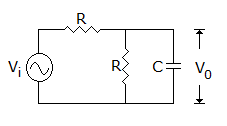
Q. For the circuit of figure the critical frequency is
Similar Questions
Explore Relevant Multiple Choice Questions (MCQs)
Q. The current through R1 is(If β = 99, VBE = 0.74 V)
View solution
Q. The feedback technique employed in the following circuit is
View solution
Q. In figure the approximate voltages of
View solution
Q. Which one of the following is connect expression of id for figure?
View solution
Q. In figure the current through resistor R
View solution
Q. For an npn transistor connected as shown in the figure VBE = 0.7 volts. Given that reverse saturation current of the junction at room temperature 300K is 10¯¹³A, the emitter current.
View solution
Q. The dc output voltage of the circuit is
View solution
Q. In figure we need an ac ground. The proper value of C is
View solution
Q. For the circuit in figure the output wave shape is
View solution
Q. In figure V0 =
View solution
Q. In figure, ID = 4 mA. Then VS =
View solution
Q. The circuit shown is
View solution
Q. The zener diode in the rectangular circuit shown in the figure has a zener voltage of 5.8 volts and a zener knee current of 0.5 mA. The maximum load current drawn from this circuit ensuring proper functioning over the input voltage range between 20 and 30 volts, is
View solution
Q. In figure, ID = 4 mA. Then VDS =
View solution
Q. In figure, V0 =
View solution
Q. In the circuit of figure diode will conduct
View solution
Q. In figure, V0 =
View solution
Q. The JFET in the circuit shown in figure has an IDSS = 10 mA and Vp = -5V. The value of the resistance Rs for a drain current IDS = 6.4 mA is
View solution
Q. In figure, V0 =
View solution
Q. In the op-amp circuit of figure, V0 =
View solution
Recommended Subjects
Are you eager to expand your knowledge beyond Electronics and Communication Engineering? We've handpicked a range of related categories that you might find intriguing.
Click on the categories below to discover a wealth of MCQs and enrich your understanding of various subjects. Happy exploring!