Question
a.
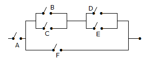
A {F + (B + C) (D + E)}
b.
A [F + (B + C) (DE)]
c.
A + F + (B + C) (D + E)]
d.
A [F + (BC) (DE)]
Posted under Electronics and Communication Engineering
Interact with the Community - Share Your Thoughts
Uncertain About the Answer? Seek Clarification Here.
Understand the Explanation? Include it Here.
Q. The Boolean expression for the circuit of the given figure
Similar Questions
Explore Relevant Multiple Choice Questions (MCQs)
Q. For the K map of the given figure, the simplified Boolean expression is
View solution
Q. In the given figure shows a 4 bit serial in parallel out right shift register. The initial contents as shown are 0110. After 3 clock pulses the contents will be
View solution
Q. The circuit of the given figure is
View solution
Q. In the given figure, A = B = 1 and C = D = 0. Then Y =
View solution
Q. The gates G1 and G2 in the figure have propagation delays of 10 n sec. and 20 n sec. respectively. If the input Vi makes an output change from logic 0 to 1 at time t = t₀ then the output wavefrom V₀ is
View solution
Q. The K-map for a Boolean function is shown in figure. The number of essential prime implicants for this function is
View solution
Q. In the given figure, the flip flop is
View solution
Q. The modulus of counter in the given figure is
View solution
Q. For the ring oscillator shown in the figure, the propagation delay of each inverter is 100 pico sec. What is the fundamental frequency of the oscillator output __________
View solution
Q. For the circuit of the given figure, the output equation is
View solution
Q. The inputs A, B, C of the given figure are applied to a 3 input NOR gate. The output is
View solution
Q. The circuit of the given figure gives the output Y =
View solution
Q. The number of product terms in the minimized sum of product expression obtained through the following K-map, where d, don't care.
View solution
Q. For the logic circuit of the given figure the simplified Boolean expression is
View solution
Q. In the circuit of the given figure, Y =
View solution
Q. If A = B = 1, the outputs P and Q in the given figure are
View solution
Q. In the given figure, Y =
View solution
Q. The minimized version of logic circuit in the given figure is
View solution
Q. In the given figure shows a negative logic AND gate. If positive logic is used this gate is equivalent to
View solution
Q. The Boolean function/implemented in the figure using two I/P multiplexers is
View solution
Recommended Subjects
Are you eager to expand your knowledge beyond Electronics and Communication Engineering? We've handpicked a range of related categories that you might find intriguing.
Click on the categories below to discover a wealth of MCQs and enrich your understanding of various subjects. Happy exploring!